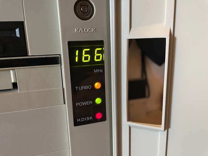
166 MHz LED readout
Back in the day when we had x86 IBM PC systems with “turbo mode”, which was really a reverse euphemism for being able to slow down the CPU clock for older applications, snazzier cases had a LED readout on the front to show the current MHz instead of/in addition to just a plain turbo LED.
These weren’t automatic at all, they were just dumb little circuits that displayed one set of numbers if the turbo lead was on and another set if the turbo lead was off. The boring people made their readouts say “HI” or “LO” so they didn’t have to bother knowing actual MHz or didn’t have enough digits. Inside the case was a group of jumpers that had to be set to turn on/off individual segments. This varies from case to case and the information for setting them up is almost lost to time, as the setup instructions are usually on a piece of paper with the case that promptly gets thrown away. Otherwise you’re left to just randomly pulling and setting jumpers to get the readout you want.
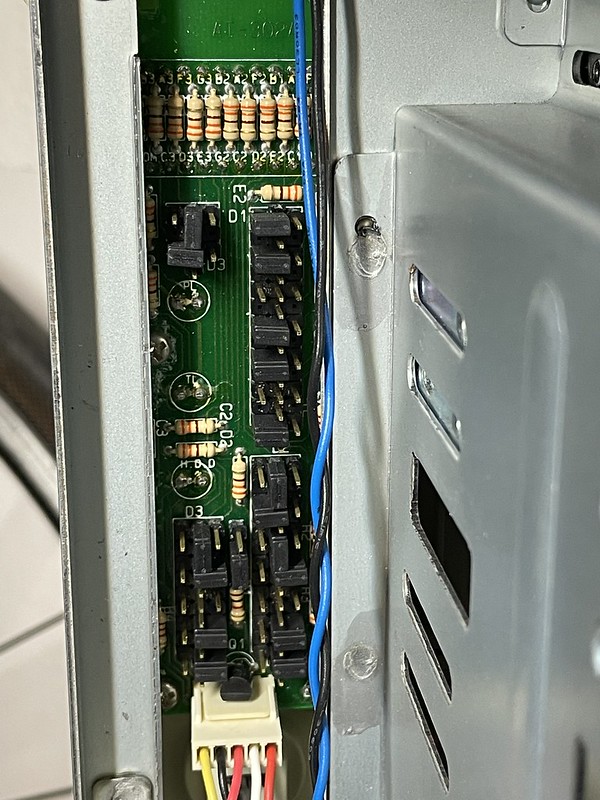
Backside of MHz readout board AT-302A
So for future google/AI searches here’s my setup instructions for my particular full tower AT case with casters, I have no better way to identify it by model/manufacturer really than that. The readout PCB is labeled “AT-302A”.
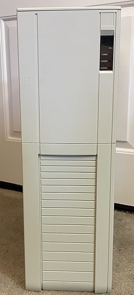
Vintage 386/486 beige full tower AT case, 5x 5.25″ drive bay, 2x 3.5″ drive bay.
This thing just screams back room closet server. You know it’s serious business because it has wheels!
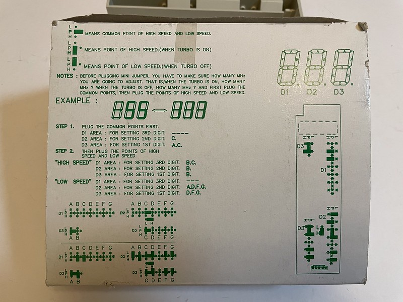
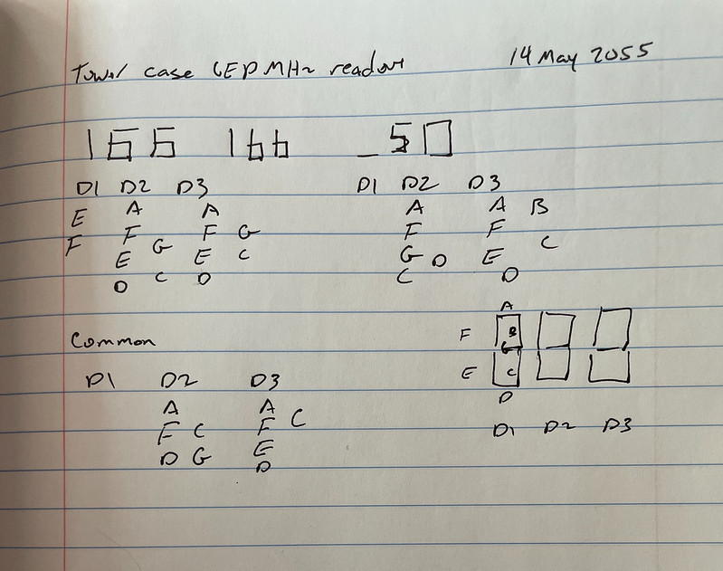
Case MHz readout setup instructions
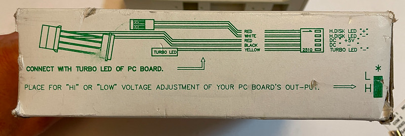
MHz LED readout power connector
Mine are printed on the box that holds all the accessories such as the wheels, screws, and drive blanks so it’s not as easily toss-able.
The PCB that contains all the LEDs gets power from a Molex drive connector, has connectors for the hard drive activity LED, and then a single negative lead that runs off to the “turbo LED” pin of the motherboard. If the pin is asserted on/off is what tells the readout board which MHz to display. In my case my motherboard has no turbo mode so I want to connect it in such a way the turbo mode LED is always “on” and speed displays “166” for my Pentium 166 MHz CPU. I have the non-turbo speed set to “50” since that’s technically the bus speed, but this is never seen except for a very brief second when the PC is turned off.
Planning the readout
As recommended I did a quick sketch of what I wanted the LED readout to show, which segments needed to be lit when in turbo mode, not in turbo mode, and which segments stay unchanged between turbo mode on/off.
Here D1, D2, D3 are the individual 7-segment LED digits, and A-G are the seven segments within each LED digit. For example on the rightmost digit, D3, I wanted this to be either a 6 or a 0. When turbo was “on” segments A, C, D, E, F, G were on, and for turbo “off” use segments A, B, C, D, E, F. The common segments between both modes were A, C, D, E, F.
On the back side of the readout where all the jumpers were, this meant A, C, D, E, F need to be set vertically across the “P” pins. B needed to be set horizontally across the “L” jumper to get “0”. and G set horizontally across the “H” jumper to get a “6”.
Repeat for all three digits.
Originally I had the “1” on the left side of the segment display and was told this was aesthetically wrong and it looked like Sid from Ice Age. I agree, so I tweaked it.
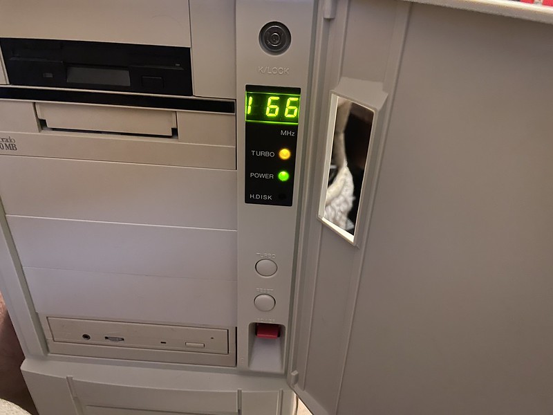
Goofy 166 version
Further case identification from the shipping box, item no TP-918D, 75.x x 31 x 55 cm:
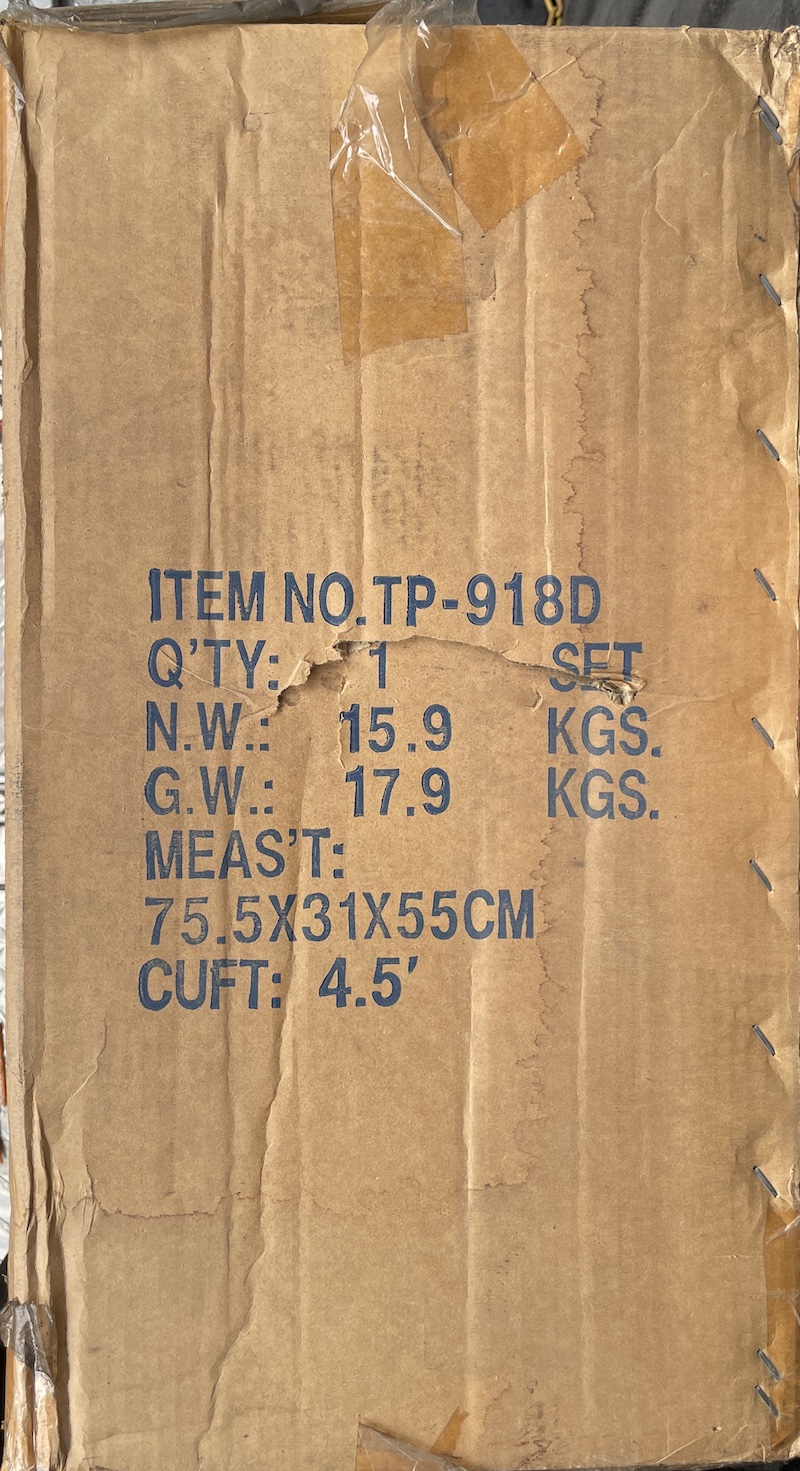
AT tower case TP-918D