Improvised drive sled
[photos: flickr – Macintosh Quara 700 drive sled]
The Quadra 700 I acquired had the internal plastic assembly that held the floppy drive and hard drives, but didn’t have the sled that the hard drive went in and clipped into the system. These are hard to find on top of an already hard to find system, lore seems to be when recyclers yank the hard drives, they discard the sleds. The Quadra 700, IIcx, and IIci all use the same sled, model numbers starting with 805-5078 or 815-5078. I checked several component places and eBay, and nobody had any for sale. You can still put the hard drive in the Quadra, there’s just nothing holding it in place preventing it from flopping around.
Fortunately lots of photos of the thing exists and it’s just a U-shaped piece of sheet metal with some holes and tabs stamped in it. It seemed easy enough to just go make one. I broke out the ruler and caliper and made some measurements of my own system. Later I discovered this post on 68kmla by Phipli who had a drawing of the drive sled which gave me the outside dimensions and let me fine tune my own measurements a bit more. Then I discovered the 3D printed version by branchus on Thingiverse (I love his Mac repair streams). I don’t have a 3D printer, and didn’t feel like going out to learn Fusion360, how to use a 3D printer, and tracking down one of our libraries just for this when I already have the metal and a metal brake. A local 3D service quoted me $38 to print one, which felt steep.
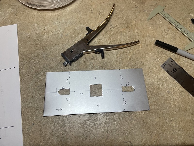
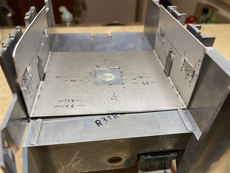
I started with a piece of 18 gauge aluminum 85mm x 196mm. I didn’t yet know how much I needed to compensate my measurements for the bending so I started working from the inside going out. I made sure the inner dimension was at least 103mm wide to allow a 3.5″ drive to slip in. First I nibbled out holes for the raised square bit at the bottom and the sides.
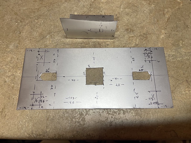
I bent a small scrap piece to figure out the bend would eat about 1.5mm, and used it to find the position and dimensions of the vertical holes where tabs would lock in. I finished marking all of these on the metal. If you can read my scribbles, that’s all of the dimensions give or take a mm.
My Dremel was utterly dead so I took shortcuts with the rest of the cutting. The OEM part had a D-shaped cut over the side humps presumably to let part of the side remain straight upright while the rest flexed, I omitted this completely. I thought a 1/2″ cold chisel would be perfect for knocking out the side tabs that would lock into the plastic assembly in the case. After a few whacks with a hammer I didn’t punch through the aluminum like I had hoped for, so I opted for the jankiest part of this whole thing by hammering a screwdriver through it!
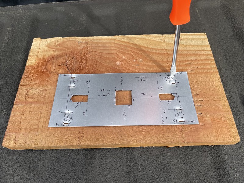 Being punched through actually worked pretty well at giving me protruding tabs on the outside surface, smoothing a bit here and there with pliers to get it just right. Next up I used my metal brake to fold the sides up. I didn’t trim the tops of the vertical pieces like the original to provide finger tabs, it seemed to fit fine without them.
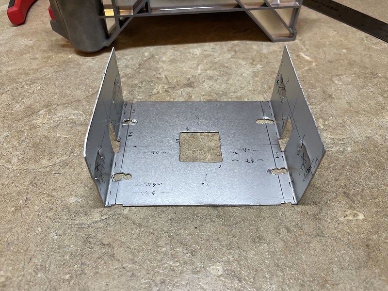
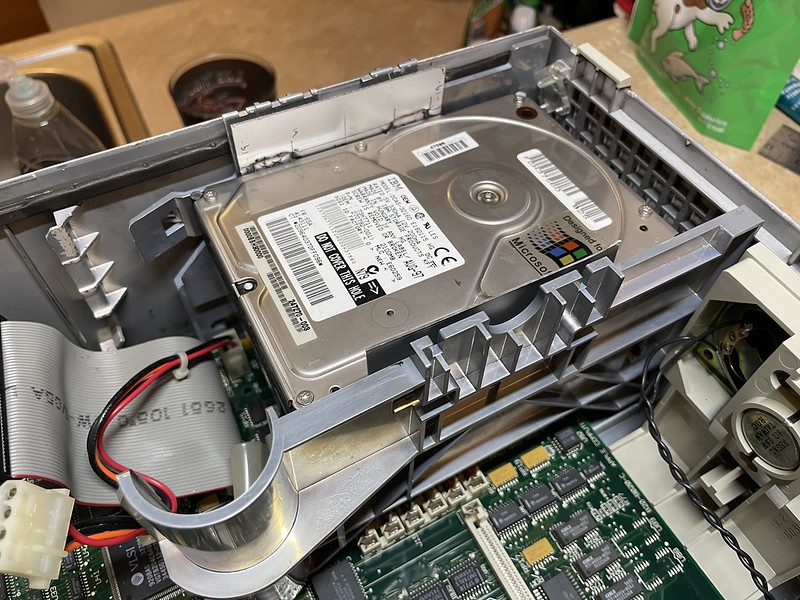
The thing actually fit into the system almost exactly the first try. I had to do a bit more nibbling on the square hole on the middle and square off my bend and it fit nicely. I messed up drilling the screw holes, so they aren’t pretty, but they work.
All in all, the thing works. I can pinch the sides to take the drive in and out, and it locks the hard drive in place. I’d say pretty good for a Saturday afternoon of tinkering around without the right set of tools. Now I can continue lurking eBay sales hoping for an original sled, or get around to having one 3D printed someday. If I had a OEM sled I would be temped to get better measurements and send off somewhere to laser/plasma cut a few dozen sleds to hand out but eh I don’t want to be in the shipping biz.
Final product