Replacement 24 V DC power supply for I-modem
TL;DR: Original US Robotics I-modem power adapter is extremely rare. I cut mine open to document it. Original adapter provides 20 V AC (1500 mA capacity) across pins 3-4 of mini-DIN connector, no other voltages. Substituting a $15 24 V DC power adapter seems to work just fine.
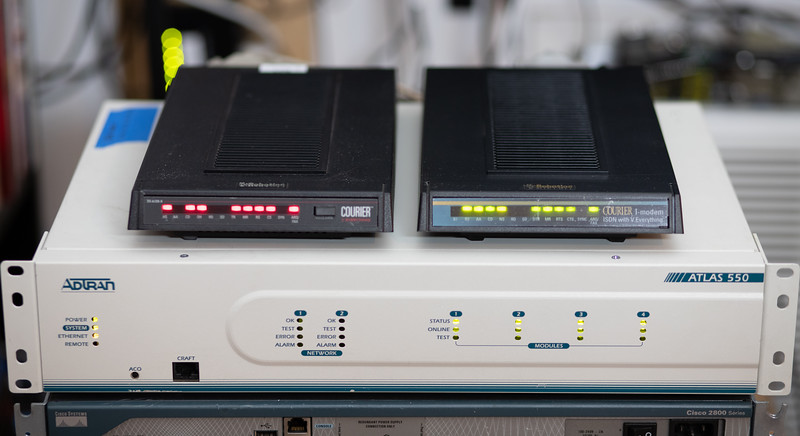
The US Robotics Courier I-Modem seems to be a unique beast in that it’s a combination ISDN terminal adapter and has a built in V.34 (upgradable to x2/V.90) modem.
Aside from normal 64K/128K data ISDN BRI service, the other unique and import part is the all digital connection which allows the modem to terminate a legit 56k modem connection, which requires one direction to be PCM. Using my Adtran Atlas 550 as an ISDN switch along with its analog FXS ports, I can connect a v.90 modem to an FXS port, the Courier I-modem to a BRI interface, and make a real V.90 call across it! I regularly get 53,333 BPS and the occasional 54,666 BPS.
The problem is the I-modems are rare and the power adapters for them are even more rare because people always split them up. They take a 6-pin mini-DIN power plug and there’s no reference online that I could find as to what kind of power they require, until now. It was hard enough even finding a silly photograph of the AC adapter with a visible part number to even get started. I got very lucky and found a pair of modems and one had the A/C power adapter. The transformer I have is made by Ault Inc, T57201500C010G, output 20 V AC, 1500 mA, US Robotics part number (P/N) 1.015.1229B. This is quite a beefy transformer, 3″ long and weighs a pound or two.
I found a couple of dubious looking places such as poweradapter dot co and uspoweradapter dot com that listed the USR part number, but when I inquired or tried to place an order for “in stock” it turned out none of them really had one in stock. Ault T57201500C020G and P/N 1.015.1317 was another similar USR power adapter I found on parts lists that may also be an later generation or alternative model. I really wish I could find an old Ault catalog to explain their part numbers!
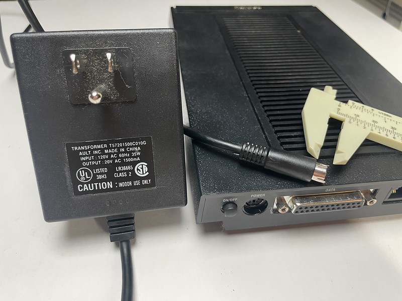
Original US Robotics Courier I-modem power adapter with mini-DIN plug
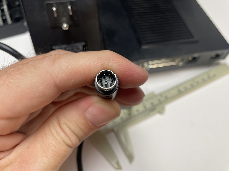
6-pin male mini DIN power plug
At first it was not clear to me if the factory power adapter only provided 20 volts AC, or if it also provided other voltages on the pins.
On the main board of the modem, there’s a group of four diodes right behind the power switch, which tells me it probably takes A/C and rectifies to DC for the components.
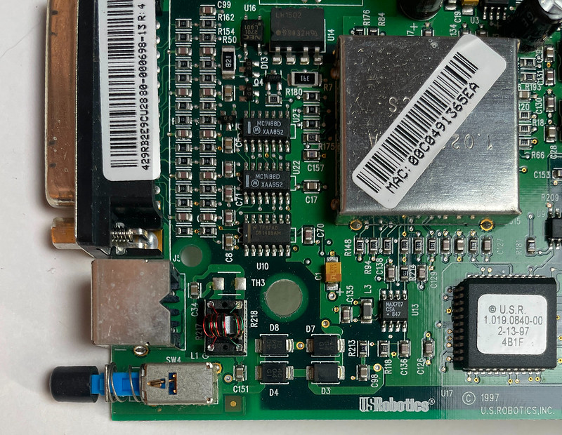
Power input of I-modem
Cutting open the transformer housing revealed a few things:
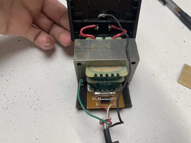
Courier I-modem power adapter inside
Inside is an isolation transformer and a small PCB with a fuse and diode (marked with 1.5 or 15?) connected to the secondary windings. There are four wires in the cable going to the DIN plug, red, white, green, black. Green is connected to the frame of the transformer, black is connected to earth ground, and these are only connected to the outer metal shell of the DIN plug, they’re not connected to any of the pins inside. White is connected to a “3” on the PCB and also to pin #3 on the DIN plug, and red is connected to a “4” on the PCB and also to pin #4 on the DIN plug. These do not have continuity to the other side of the transformer.
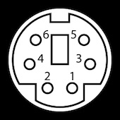
Mini DIN-6 pinout
Somebody suggested to me that the diode may be acting as a rectifier to provide only a half-cycle waveform as sort of a cheap way to get DC-ish power. I thought maybe this was why the power transformer was so hard to find, this weird half-wave output thing. But also does this mean I could just feed DC power into the modem?
I wanted to see the waveform of the power output before I got too deep into trying to find or craft an exact replacement. Being a new oscilloscope user I had read all the warnings about connecting probes to an AC transformer and AC mains and put it off for a while. Finally after careful probing with a multimeter I was pretty sure I could hook things up safely so gave it a shot, connecting my probe to pins #3 and #4 on the DIN connector:
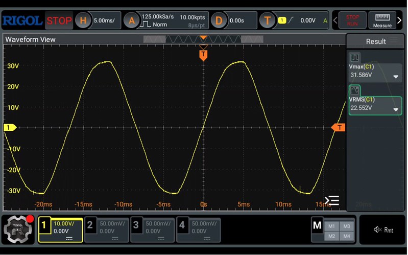
Power supply output
I was expecting to see some sort of flat rippled half-cycle thing, but no, there’s a full normal AC waveform there, peaking out around 32 V and 22 V RMS. So the AC adapter really is outputting normal AC power.
Running a photo of the transformer through ChatGPT suggested the diode and fuse inside the transformer housing were wired across hot/neutral as a form of circuit protection. Through some other legit-looking math, it suggested 24 – 27 V DC could be an acceptable substitute, which sounded right to me.
It was suggested today on the The Serial Port Discord that this could be a transient-voltage-suppression diode to protect the modem from over-voltage.
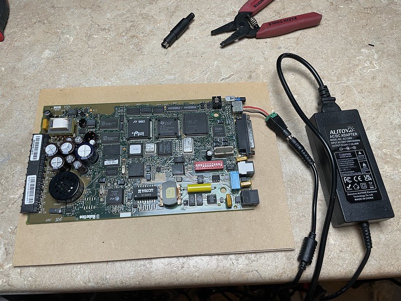
I wanted to see if the thing would run on 24 VDC, so I ordered a power adapter to try it out. I’m pretty sure the thing will run on another plain 20 V AC power adapter, but ones with AC output are slightly harder to find and/or require some buck adapters to get the right voltage (such as a 24 V AC Nest/Ring doorbell transformer). There are other US Robotics 20 V AC-AC adapters but their rated capacities top out around 500 mA, not enough for the I-modem.
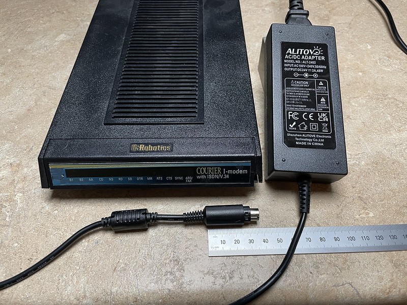
Powering up
The new DIN-6 plugs I received from Amazon had square-ish pins so they didn’t fit, so I just chopped off some short wires to shove in the modem power socket in the meantime. I hit the switch and it all came to life!
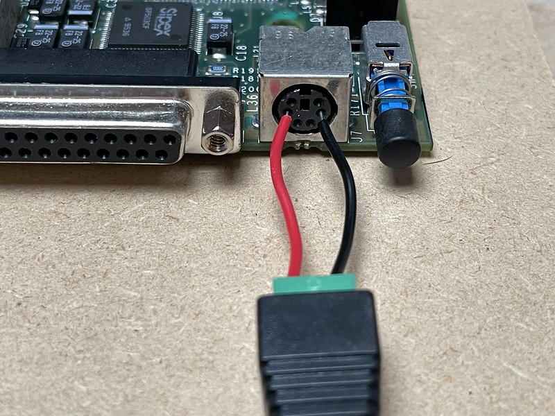
DC adapter to “outermost” pins 3-4
Responding to AT commands was a good start, I started testing through various ATI commands and all seemed to be working:
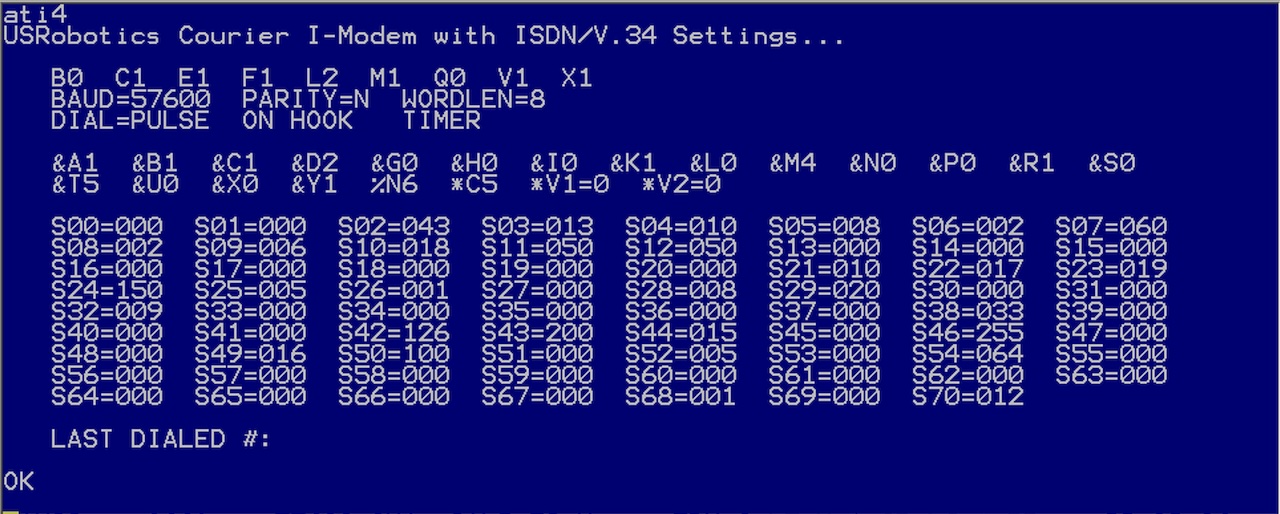
ATI4 commands with new power adapter
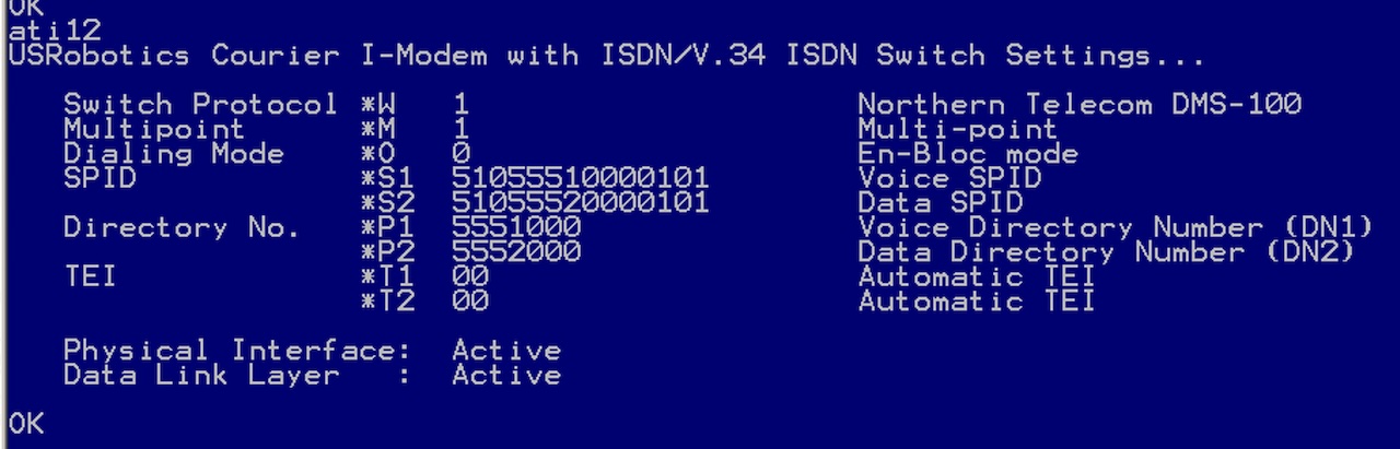
ATI12 ISDN status
It had already brought up ISDN with my Adtran Atlas, didn’t seem to have any issues there.
I tested writing to NVRAM by writing AT&B1&W, resetting the modem with ATZ, and then verified it was there, then did a AT*P2 to change one of the ISDN numbers, issued an ATZ! to reset it and verified the new value came back. I’ve seen this sort of thing fail, writing configuration to NVRAM, on other devices when they were fed with DC when they were expecting AC voltage.
Pro tip: when configuring ISDN it’s really nice that on the ATI12 screen they list all the *-commands to change the different settings so you don’t have to go digging for the manual.
Next was to bring up a modem call to see if that worked, and it did! Connected to it at 53,333 BPS using V.90.
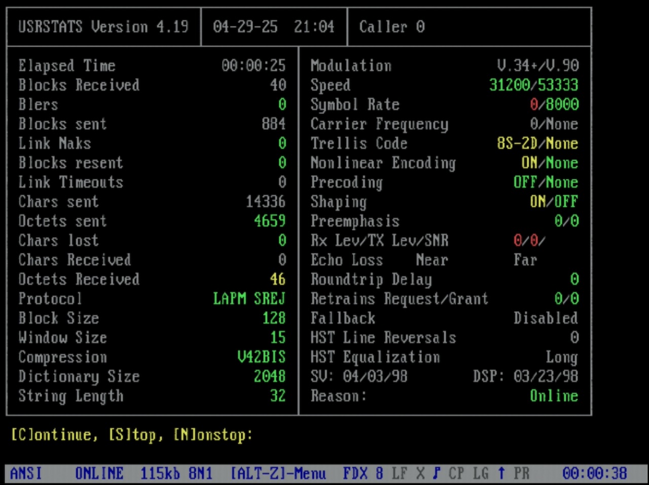
USRSTATS on V.90 connection
I downloaded a couple of megabyte sized files across it, and it all seemed to work.
I tested this 24 V DC power adapter on both Courier I-modems I have and both seem to work as expected. I’ll continue to test with it, but so far it seems a DC adapter will work.
24 V DC adapter with new mini-DIN plug
V.90 call made across Adtran Atlas 550
Model notes
I’ve pointed this out on my modem teardown collection and I’ll call it out here too. There are at least two different external revisions of the US Robotics Courier I-modem:
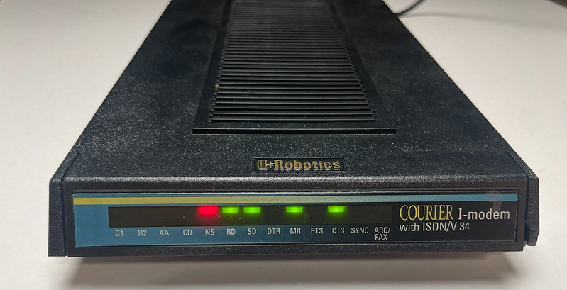
Version 1: US Robotics Courier I-modem with ISDN/V.34
One is the “Courier I-modem with ISDN/V.34“. FCC ID CJE-0313, P/N 1.020.195-B. The one I have has a green/gold PCB with board P/N 1.012.0313-E, copyright 1995. It has an Intel i386 EX, a TI DSP, and a Sipex SP503CF IC chip handling RS/EIA-232 and V.35 serial comms.
The bottom of the unit has 12 DIP switches for controlling AT commands, boot settings, and whether or not it speaks V.35 or EIA-232 on the serial port.
ATI3 reports “US Robotics Courier I-modem with ISDN/V.34”. ATI7 reports 20.16 MHz processor, 768k EPROM, 256k RAM.
Leaky cap warning: the 1995 board had two 47 uF / 63 V electrolytic capacitors, C92 and C140, that had started to leak onto the PCB. There was some minor trace corrosion around C92 that I had to re-tin, other caps looked ok. C140 in particular was difficult to remove because it was in the middle of a huge ground plane, so this is why I didn’t bother recapping the whole board. If you get one I recommend opening it open to take a look at all the capacitors.
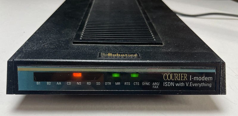
Version 2: US Robotics Courier I-modem ISDN with V.Everything
The other is the “Courier I-modem ISDN with V.Everything“. Also FCC ID CJE-0313, P/N 1.020.0396-00, model number 0698-1. This one is more of what I call a green/dark green PCB/mask with board P/N 1.012.0511-B, copyright 1997. It still has the Intel i386 EX, but it’s not clear if the TI DSP is still there or was replaced with another chip. There’s a metal can on one chip that I haven’t lifted up to see what it’s hiding. Instead of the Sipex for serial, it has more traditional MC1488D AND MC1489AD line drivers. Presumably because it only supports EIA-232 and not V.35.
The bottom of the unit only has 4 DIP switches for controlling the AT command set and boot settings.
ATI3 still reports “USRobotics Courier I-modem with ISDN/V.34“, ATI7 20.12 MHz processor, 768k EPROM, 256k RAM. This one is upgraded to x2/V.90, ATI7 reports HST,V32bis,Terbo,V.FC,V34+,x2,V90 with a supervisor rev of 2.7.6 and DSP rev 3.0.4.
I haven’t tried but I’m assuming the boards are probably functionally identical and they can both be upgraded to V.90.
Edit: 5/5: I was able to update my first gen “with ISDN/V.34” to 2.7.6 firmware and it now supports x2 and V.90.