TL;DR: re-re-patching vintage Turbo Pascal programs so they work in modern times on modern hardware
Wildcat! v4, a MS-DOS based bulletin board system was written in the 1990s in Borland Turbo Pascal and was not completely Y2k compatible. Internally the Wildcat! database understands the four-digit year just fine. (Wildcat! was not the only BBS software with Y2K issues.) The problem specifically is when dropping to an external program such as a door and returning, it reads/writes a session state file called SYSINFO.DAT which contains two-digit years. So when Wildcat! loads back in it sees the caller has been on since, say, 1/21/15, it thinks they’ve been on since 1915, a hundred years beyond their allowed time limit and punts them off. It also affects bulletin read state somehow, prompting you that almost all bulletins have been updated since your last call.
Fortunately there’s fixes for this to make Wildcat! work in the modern age by permanently manipulating the internal epoch year so that everything earlier than say year x/x/26 is really treated as 2026 and not 1926. One such program is called PatchWC! by Joe Martin of Via Software, commonly distributed as PWC300.ZIP (local copy). (See note below about why this doesn’t work in DOSBOX-X)
Another patch for Wildcat! that is almost always needed is to get around the Borland Turbo Pascal “Runtime Error 200” on modern hardware, which is a separate problem than Y2K.
I had actually patched my binaries a couple of times, first with an older version of PatchWC! v2.00 that only worked until Jan 1, 2025, a year ago. I had sworn I had used his v3 tool but didn’t. I re-patched using the v3.0 tool last year to get TuxedoCat Lounge BBS working again, but apparently I didn’t pay attention to the threshold year and things broke again on this week on Jan 1, 2026. The v3 tool has logs from my last run that clearly said “Updated WILDCAT.EXE threshold from 1900 to 1925“.
So, I’ve patched yet again, this time which should handle all the way out to 2040. Normally this would be at the cost of anyone with a birthday before 1940, but I don’t collect birthdays and pretty sure I don’t have any users that old.
The v3.00 utility is a huge improvement over the v2.00 tool. The previous version pretty much ran in your C:\WILDCAT directory, did a bunch of stuff, and returned. The newer version is clearly intended to support multiple types of patches someday, has menus, can tell if individual binaries are fixed, and keeps logs.
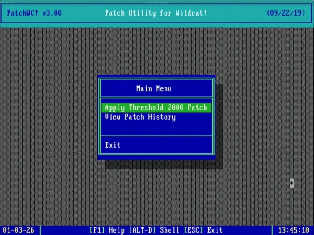
PatchWC! v3.00
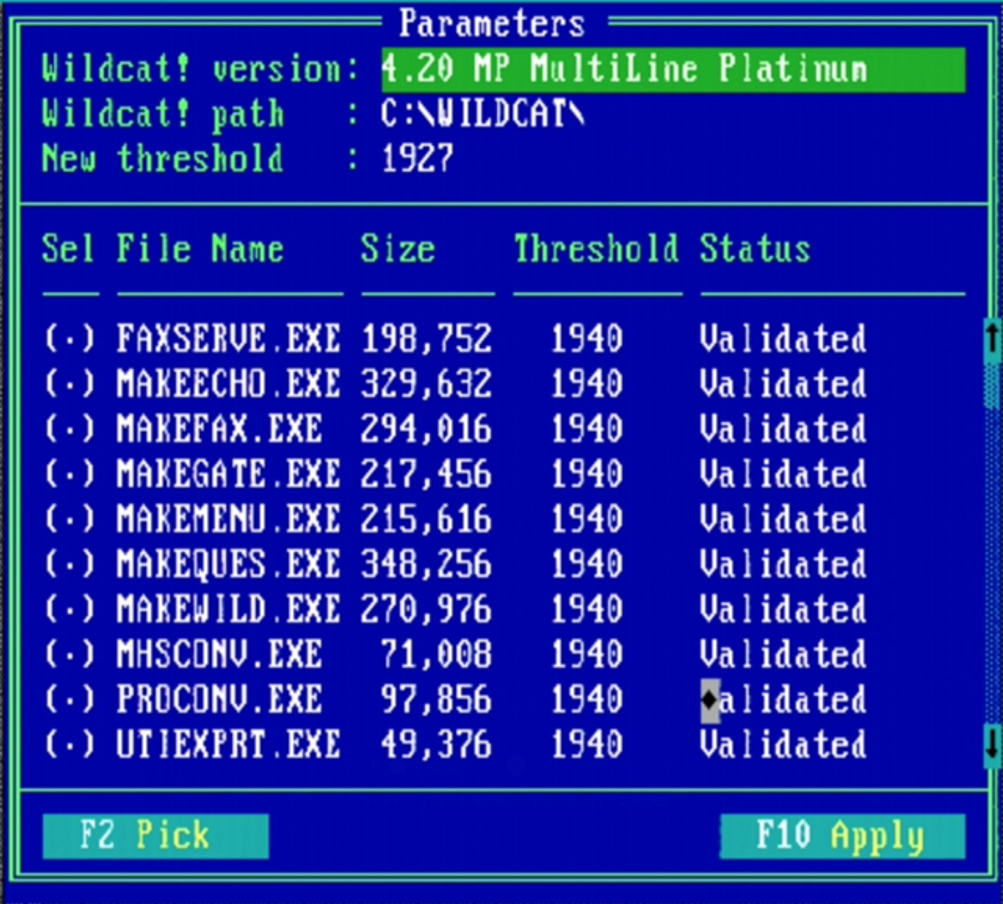
PatchWC! threshold adjustments
Once the new threshold is applied, it looks something like this in the log file:
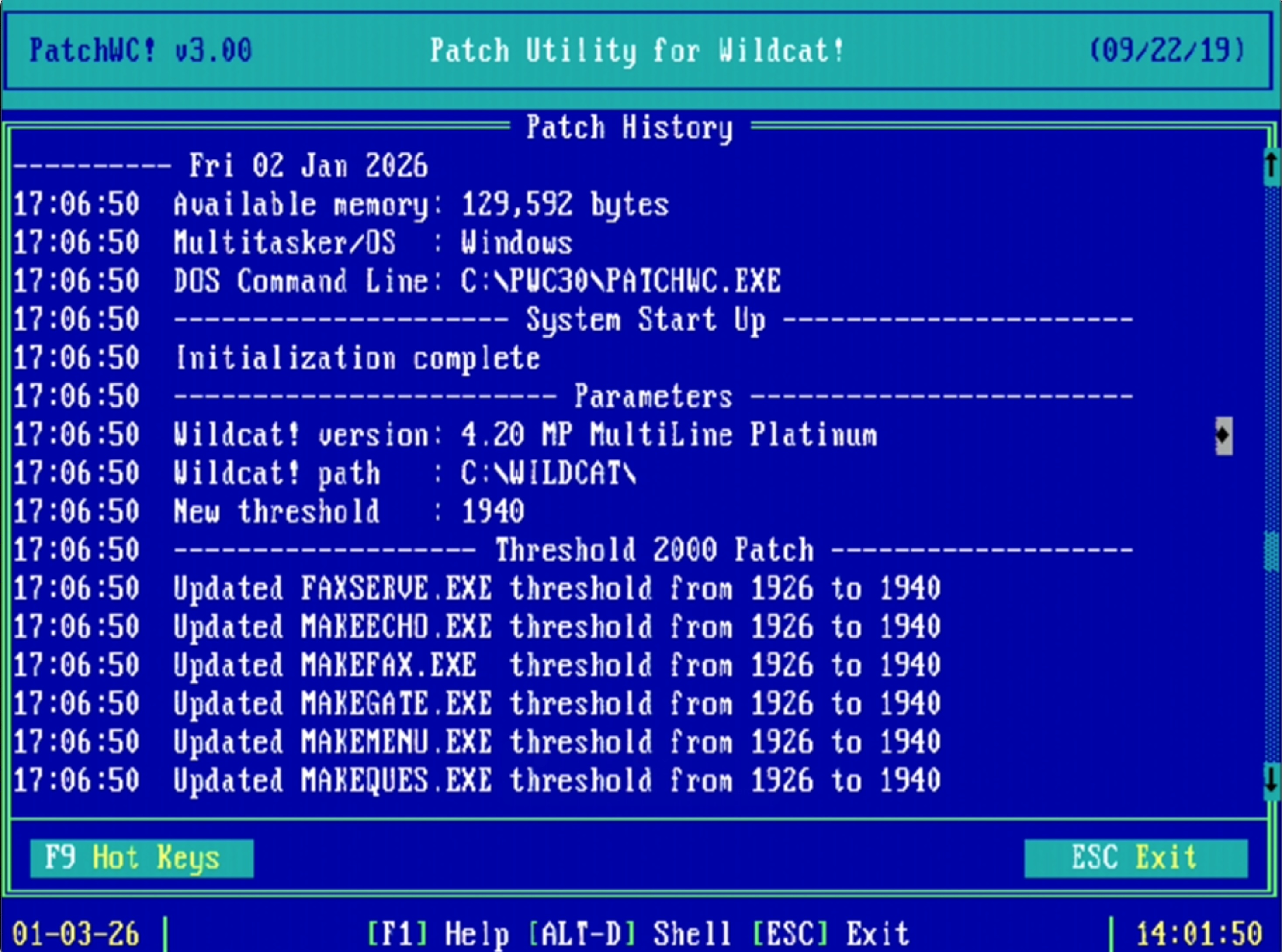
PatchWC! v3.00 log
Here’s what the previous v2.00 tool looked like:
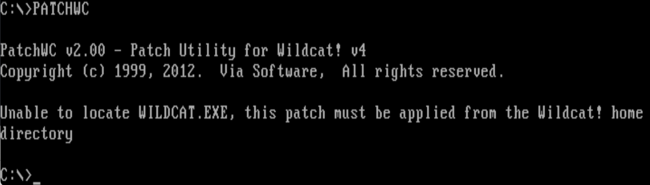
PatchWC v2.00
Of particular note the PatchWC tools may be picky on what versions of Wildcat! they’re run against. I want to say based on some forum posts that maybe v2 only worked on Wildcat! v4.0/v4.1 and v3 only worked on v4.2, but I do not know. Strings I dumped out of v3.00 lead to me to believe it might be aware of a wider set of version numbers.
Once this is done the binaries are ready for the post-Y2K world, but in my case I need the Pascal Runtime 200 patch re-applied. (I’m not sure if PatchWC! reverts the runtime patch or if my backup copy of binaries didn’t have the Pascal patch already applied).
Borland Pascal Runtime Error 200 patch
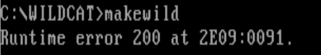
Runtime error 200 at 2E09:0091
There are at least two tools to patch Borland Pascal .EXE files to fix the runtime 200 problem, one is PATCHCRT.EXE from Kennedy Software. This has been reliable for me, but has the annoying problem of requiring tapping through screens and only operating on a single file at a time. In the case of Wildcat! there are a couple dozen .EXE files that need to have PATCHCRT run on them, so the only option is to just hunker down, keep pecking away, and do them one at a time until you’re finished. Further aggravating matters is that some .EXE files may be PKzip compressed and need UNP.EXE to restore them before PATCHCRT can work. Other info about this problem is on the PC Micro website via the wayback machine.
Normally trying to run an unpatched .EXE file on a fast, modern (allegedly beyond 200 MHz) system results in the program exiting with something like Runtime error 200 at XXXX:XXXX.
I’d recommend copying C:\WILDCAT\*.EXE to somewhere as a backup.
Here’s running PATCHCRT.EXE WILDCAT.EXE:
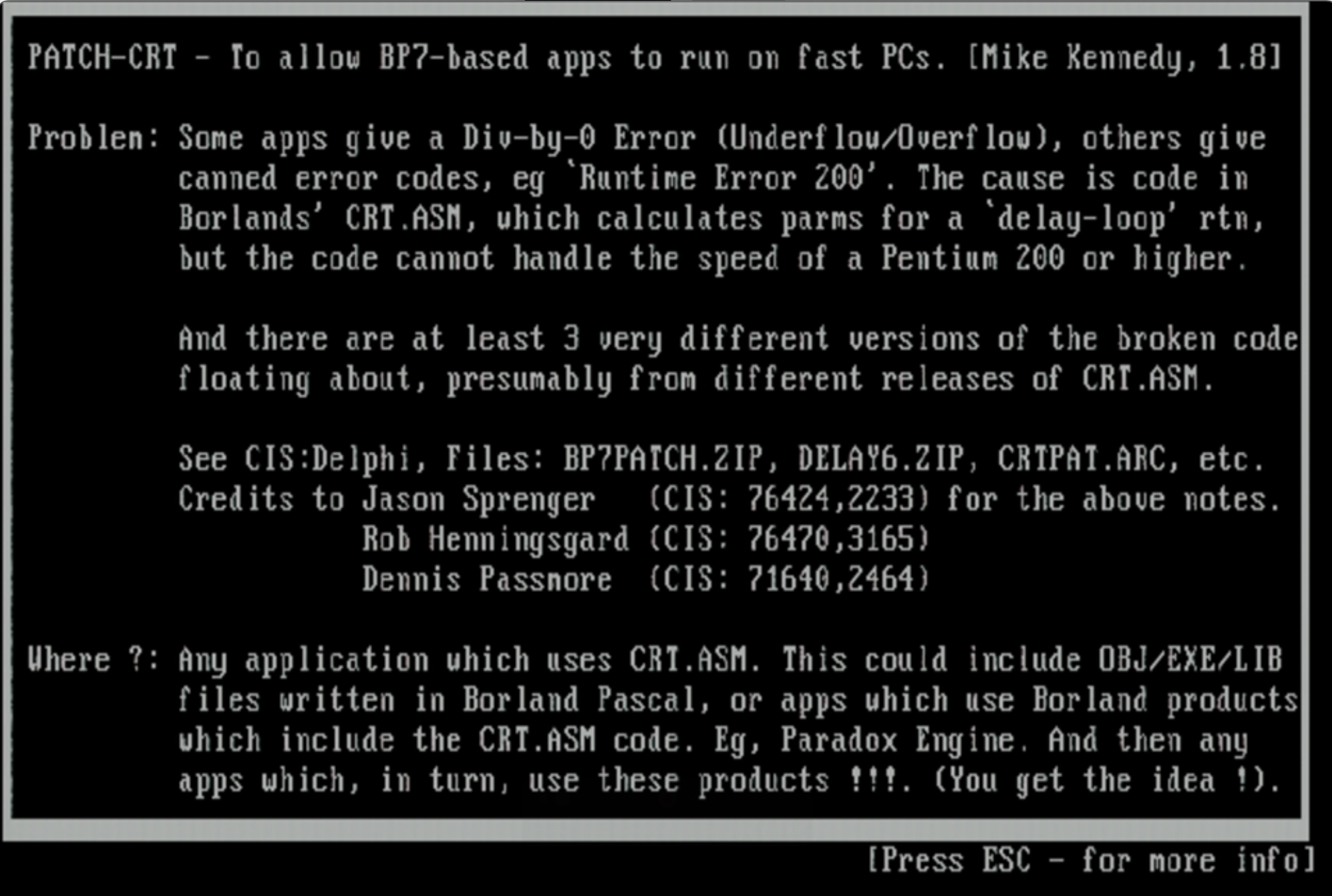
PATCH-CRT
This is what it looks like after a Wildcat! binary has been patched:
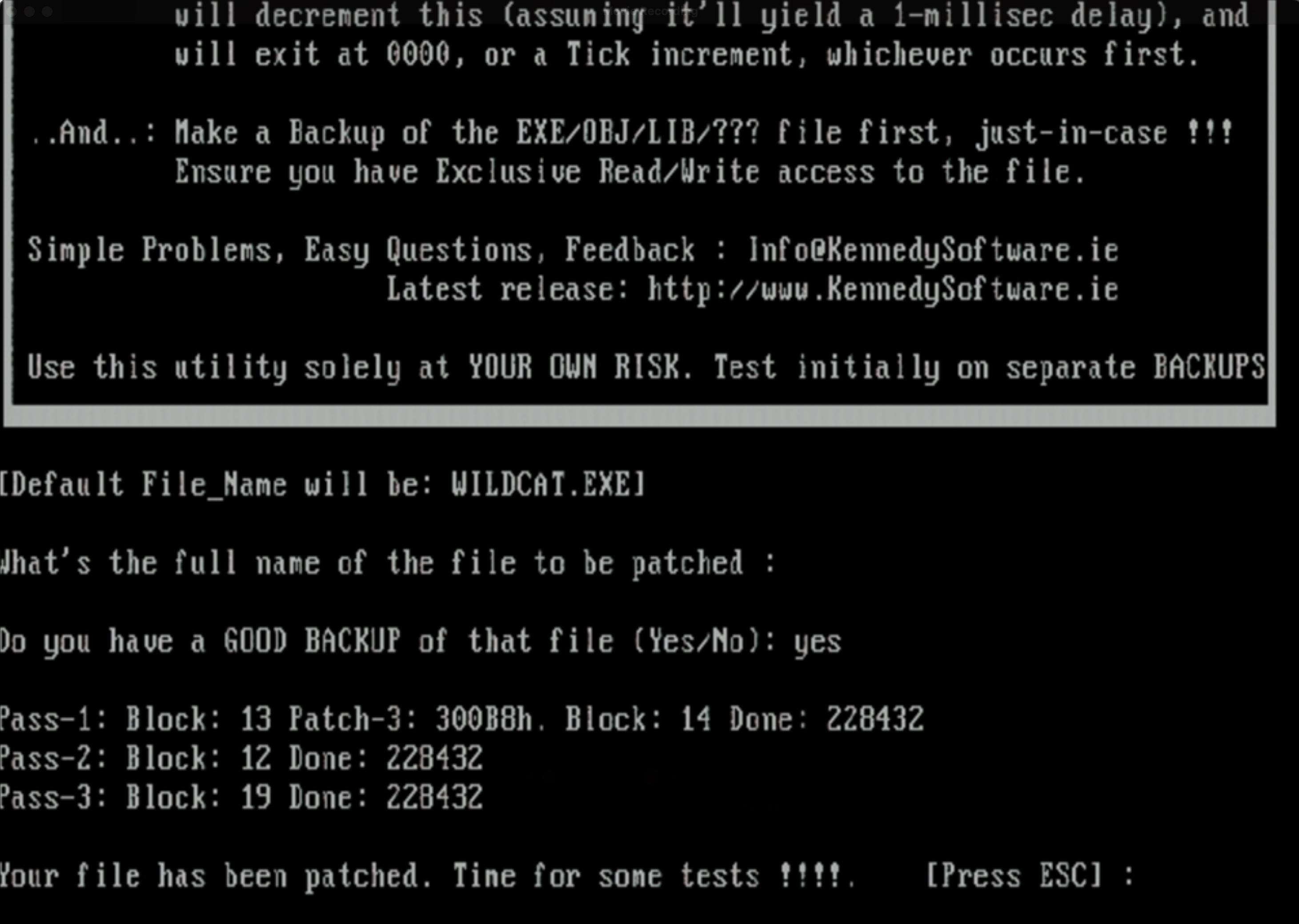
Patch-CRT on WILDCAT.EXE
Now that both the Y2k and runtime error patches have been applied, all the binaries can be copied to your C:\WILDCAT directory, restart everything and you’re good to go.
PatchWC! v3.00 and BTInitIsam error
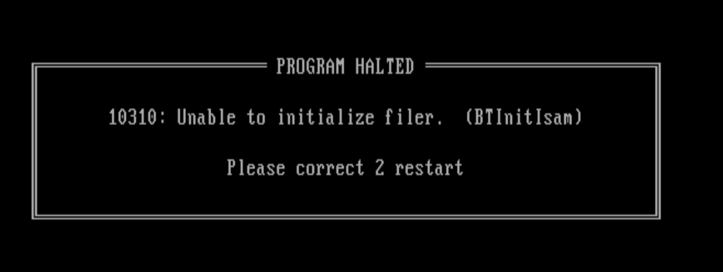
BTInitIsam message
Why doesn’t PatchWC! v3 work on DOSBOX-X, is it possible to make it work?
It seems reasonable to fire up a DOSBOX-X session to do this patching work. For whatever reason when I try to run PatchWC in DOSBOX or even when booting Windows 95 to a command-prompt only session I get the cryptic error “10310: Unable to initialize filer. (BTInitIsam)“. This does not happen when I run the program while the Windows 95 graphical shell is running and I do it from a command prompt. The number seems to change in “Please correct X restart” but I have’t been paying attention to when it’s a 1 or a 2.
Starting SHARE.EXE support in DOSBOX-X doesn’t help. I haven’t found any suitable answers on Discord nor Facebook for why this happens and I know other people encounter it too. It’s possible this affects other Turbo Pascal programs too. For the sake of learning more how to debug MS-DOS executables I started poking at this more to see why this is happening.
In fact, here’s all the places I’ve tried it out of curiosity to see what is going on:
- MS-DOS 6.22: PatchWC runs successfully!
- MS-DOS 6.22 with SHARE.EXE: PatchWC loads successfully!
- Windows 95, 32-bit GUI loaded, MS-DOS shell: PatchWC loads successfully!
- Windows 95 DOS (no 32-bit shell loaded): 10310 error
- Windows 95 DOS (no 32-bit shell loaded) with Netware 4.0 client running: 10310 error
- DOSBOX-X with SHARE support: 10310 error
- DOSBOX-X with SHARE, NE2000, and IPX support: 10310 error
- DOSBOS-X with Windows for Workgroups 3.11, Microsoft Network, IFSHLP.SYS and NET START: 10310 error
- DOSBOX-X booted into FreeDOS 1.4: 10310 error
PATCHWC.EXE itself is a PKzip-compressed binary, so it takes UNP.EXE to extract the real .EXE file to start poking around. Running strings on this didn’t turn up anything interesting, but strings on the PATCHWC.OVR file. This uncovers some interesting text:
)Unable to initialize filer.  (BTInitIsam)
: 2Unable to create buffer.  (BTSetVariableRecBuffer)U
@RP1
.DAT
Unable to create database!
Unable to open database!U
BTCloseFileBlockU
^L DATABASE :
.  #:
BTREE ERROR ->
Unable to lock database!
Which leads me to believe “BTInitIsam” refers to B-Tree and ISAM.. Last year I spent a bunch of time trying to find this and it lead me to TurboPower B-Tree Filer, but I didn’t bookmark it and Google is utterly useless now. Google will endlessly insist “did you mean British?”
A few hours later
Ok no thanks to Google I found some Pascal notes where I was working on this problem last year.
In the Turbo Pascal B-TreeFiler v5.5 User’s Manual we have the function BTInitIsam:
BTInitIsam function
This is talking about emulating a network. Inside the B-TreeFiler v5.5 source code and docs we have these matches for “10310”:
basic147: tpbtreefiler_5_55 bwann$ fgrep 10310 -R *
doc/errors.txt:10310   4     Network initialization error (BTInitIsam)
doc/errata.txt:Q: What does IsamError 10310 really mean?
doc/Help/filer.hxt:10310  (4)    0202BTInitIsam
source/FILER.INC:      IsamError := 10310;
source/FILER.INC:      IsamError := 10310;
source/ISAMTOOL.PAS:          10310 : IsamErrorMessage := 'Netz-Initialisierungs-Fehler';
source/ISAMTOOL.PAS:          10310 : IsamErrorMessage := 'Network initialization error';

and this

Q: What does IsamError 10310 really mean?
A: BTInitIsam was unable to find the network you specified as the
   first parameter. For Novell this means that proper shell wasn't
   found (either NETX or the VLM Requester) or that a server that has
   been logged in to was not found.
Why Google can’t find that anymore is a sorry state of affairs.
More notes: BTInitIsam calls IsamInitNet in ISNETSUP.INC, which then has a case statement for NoNet, Novell, MsNet. Inside NovellInitNet we have a VLM suppport check and a thing called IsamInstallInt24Handler. MsNetInitNet funnily just seems to do no checking and always returns MSNetInstalled if it’s configured in the FILER.CFG file.
function IsamInitNet(ExpectedNet : NetSupportType) : Boolean;
begin
  case ExpectedNet Of
    NoNet  : IsamInitNet := NoNetInitNet;
    {$IFDEF Novell}
    Novell : IsamInitNet := NovellInitNet;
    {$ENDIF}
    {$IFDEF MsNet}
    MsNet  : IsamInitNet := MsNetInitNet;
    {$ENDIF}
  else
    IsamInitNet := False;
  end; {Case}
end;
From the DOSBOX-X debugger it looks like it’s making a ton of INT 21h calls around this time, so it seems to be getting something here triggering the network detection.
…no luck so far. I wish I knew enough about IDA Free or the DOSBOX-X debugger to poke at this more.
Tags: bbs, wildcat, y2k


