Over a recent couple of weekends I built a thing to measure the current and voltage of the components of a 12V solar/PV power system. Ever since I started using solar power at Burning Man I wanted to get a good measure of how much I was consuming and how much was left. At the time I settled on a Morningstar charge controller with LCD voltage meters to tell me.
This new setup adds data recording+logging into the mix, something I’ve always wanted. Here, the measurement modules are attached to a Raspberry Pi via i2c and a simple python script collects the data and sends it wirelessly to OpenTSDB for storage and charting.
The hardware and other bits, excluding the Pi, ran me around $50-$60. Allegedly this setup should handle about 3 amps, although if somebody wants to do the arithmetic and make an appropriate shunt they should be able to measure much higher currents.
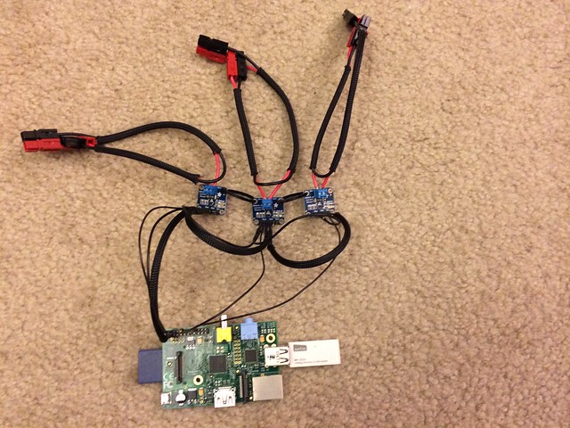
At the heart of the setup are three INA219 (“high side DC current sensor”) modules from Adafruit which do the measuring, one each for the solar input, the battery, and load. They’re about 1″ square, have a terminal on the board for wiring in-line in electrical circuits to measure, and have a small shunt and chip that measures the voltage and current. The bulk of my time was spent making a wiring harness for this setup to plug into my existing solar setup and soldering on all the connectors. I personally insist on everything I have use Power Pole connectors so if one were less inclined they could avoid a lot of work. Working with the rest was relatively quick work. Adafruit has some excellent tutorials on wiring up and working with the INA219, which is where I got the majority of my information.
Each of the INA219 modules speak i2c to the RPi and the SDA/SCL pins daisy-chained with continuous jumpers back to the respective i2c pins on the RPi (P3 and P5) to form an i2c bus. Two have solder junctions to set the i2c address, resulting in the three being accessible on the bus at 0x40, 0x41, and 0x44. Also to power the INA modules themselves, another set of continuous jumpers connect Vcc and GND back to the 5v and GND pins of the Raspberry Pi. Adafruit has a generous tutorial on how to connect and verify i2c is working. For the most part it was painless and simple, enable the i2c kernel module and the three INA modules just showed up when I ran “i2cdetect -y 1”.
The few software libraries for the INA219 and i2c assume use with an Arduino, but some dude over on Github did a nice Python port of the INA219/i2c library. However, there looks to have been a bug in the original Arduino version regarding two’s complements and the code on Github needs a slight patch to properly measure negative voltages. (note to self, submit a patch). Once that’s sorted out, it’s just simple Python method calls to get instant voltage and current information.
A quick example to query the three INA219 modules looks like:
#!/usr/bin/python

from Subfact_ina219 import INA219

for i2caddr in ['0x40', '0x41', '0x44']:
    ina = INA219(address=int(i2caddr,16))

    print "== %s " % i2caddr
    print "Bus voltage: %.3f V" % ina.getBusVoltage_V()
    print "Shunt voltage: %.3f mV" % ina.getShuntVoltage_mV()
    print "Current: %.3f mA" % ina.getCurrent_mA()
    print "Voltage: %.3f V " % ( ina.getBusVoltage_V() +
        ina.getShuntVoltage_mV() / 1000 )
To get the voltage of the thing you’re measuring, you must add the bus voltage and shunt voltage to get all the components of the measurement. Also, you must wire grounds of the battery, solar panel, load, and the Raspberry Pi together to be able to measure individual voltages. (Something I forgot to realize for a long time.) Otherwise you only get electrical current data, voltage is indeterminate.
root@solar:/home/pi# python power.py
== 0x40
Bus voltage:   12.420 V
Shunt voltage: -37.270 mV
Current:       -373.000 mA
Voltage:       12.383 V
== 0x41
Bus voltage:   12.548 V
Shunt voltage: -37.160 mV
Current:       -372.000 mA
Voltage:       12.511 V
== 0x44
Bus voltage:   12.416 V
Shunt voltage: 1.000 mV
Current:       10.000 mA
Voltage:       12.417 V
Here, module 0x40 is represents the load, 0x41 is the battery, and 0x44 are the solar panel. There’s a string of 12V LED lights hooked up right now, drawing 373 milliamps. Likewise there’s a 373 mA draw on the battery. The solar panel is in shade so it’s only contributing 10 mA right now. The negative values are a handy indicator of the direction of the current, i.e. when the battery is charging the values are positive, when it’s being discharged the values are negative.
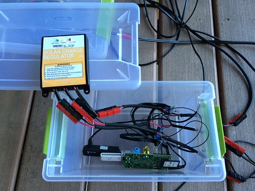
For the small solar setup, I’m using a solar panel and charge controller from Harbor Freight. Their 7A charge controller features a low voltage disconnect (something I required for this setup), is compact and pretty inexpensive. It fits tidily into the plastic container which temporarily houses the RPi and modules. This will work with any charge controller. Another container holds a small 12V battery. [Edit: I have my doubts about the LVD feature of this charge controller after it apparently let my battery get down to 6 VDC under load overnight. >:( ]
Note: at the time the Raspberry Pi is not solar/battery powered, nor can it switch on/off any of the loads. I have an USB power cord running inside to power the setup. It should be easy to rig up a voltage converter, but that’s a project for another time. This would make it a real standalone unit and be quite handy and adapted into other real applications.
 For the data storage, I wrote a Python tcollector script for OpenTSDB which polls the INA modules every 15 seconds and records the values to a database. Using the built-in plotting tools, I can quickly visualize current or historic solar production or power consumption. The shameless cut-n-paste tcollector I wrote is over on my Github page.
The script prints a ‘ina219’-prefixed metric name, timestamp, tags and data suitable for use in a time series database:
ina219.shunt_voltage 1396837555 0.050 address=0x40 name=load
ina219.voltage 1396837555 12.672 address=0x40 name=load
ina219.bus_voltage 1396837555 12.672 address=0x40 name=load
ina219.current 1396837555 0.000 address=0x40 name=load
ina219.shunt_voltage 1396837555 -0.690 address=0x41 name=battery
ina219.voltage 1396837555 12.671 address=0x41 name=battery
ina219.bus_voltage 1396837555 12.672 address=0x41 name=battery
ina219.current 1396837555 -7.000 address=0x41 name=battery
ina219.shunt_voltage 1396837555 0.130 address=0x44 name=solar
ina219.voltage 1396837555 12.672 address=0x44 name=solar
ina219.bus_voltage 1396837555 12.672 address=0x44 name=solar
ina219.current 1396837555 1.000 address=0x44 name=solar
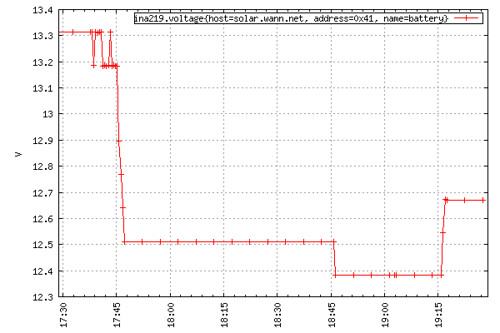
Two-hour plot of battery voltage while connected to load of lamps for an hour:
Eventually I’d like to have a battery charge monitor, but this involves getting the temperature of the battery to take into account.
Hi Bryan,
I wanna thanks for your explanation, i congratulations for your project. Your code, i used but with reference for my work because you deserved.
Best Regards ;)
Hi,
I am interested in making a project like yours to monitor my solar panel charging my battery for my propogation system.
If i wanted to read higher currents would you still recommend a INA169 or another product to work with the Raspberry PI 2?
Do you have any updated wiring diagrams or software for your project?
Any help would be appreciated.
I’m not familiar with the INA169, but offhand it looks like it will get you a couple more amps if that’s all you need. Any Raspberry Pi can do this, they all support I2C devices.
Ideally for measuring larger currents you’d use a shunt resistor where the bulk of the current would go over the shunt and a small (but accurate and predictable) amount of current would be measured off the shunt terminals.
For example (making up numbers here) in a circuit carrying 30 A, 29.5 A would pass over the shunt and .5 A would go to the INA module. You’d need to know the resistance of the shunt and then multiply the resulting numbers appropriately. In a solar + battery + load setup, you’d need three separate shunts for each of the three measurement points.
For wiring, I don’t have any diagrams (I should do this). From what I remember, it goes something like this:
– Raspberry Pi 5V pin provides power (Vcc) and ground to the INA boards, using daisy chain jumpers
– Another set of daisy chain jumpers links I2C from the RPi to SCL/SDA on the INA boards, and back to the RPi
For the load side, the INA modules (or your shunt) would be wired in-line with the positive lead, e.g.
Battery(+) -> INA Vin(-) -> INA Vin(+) -> charge controller
Solar(+) -> INA Vin(-) -> INA Vin(+) -> charge controller
Load(+) -> INA Vin(-) -> INA Vin(+) -> charge controller
Depending if you want positive/negative numbers on your readings, you can flip which side of the Vin your positive is connected or just do it in software, e.g. maybe
Load(+) -> INA Vin(+) -> INA Vin(-) -> charge controller
The important part is that of the grounds need to be connected together, otherwise the INA has no voltage reference and you’ll get false readings.
Adafruit has several really good examples of how to work with I2C on the Raspberry Pi, and some examples of working with the INA boards.
Hrm, my lines are producing 20 amps. Where’s a damn board for something like that? Then again I’m also doing 4.5kw of solar and will be doing 2.25kw of wind here soon.
Anybody have any information on where I can find something of that nature? I have a spare pi and a spare beagle that I can use for processing.
I’d also like to utilize syslog (RFC 5424) for output so I can have logstash munge what ever information I receive and plot out within kibana.
I have a couple of INA219 boards that I am using on a robotics project. I’m using a Raspberry pi and have downloaded the Subfact_pi code from the github site you reference above. My voltage readings seem quite random, going from 3v to 29v with each reading (I’m running a 12 volt battery), but the current seems to be accurate. When I use Adafruit’s Arduino setup the board is accurate! I’ve combed through the ported python code and compared it to the Arduino code and can find nothing. Any ideas? I’m at wit’s end.
Hi,
First of all Happy New Year :)
Thanks for your explanation and congratulations for your project.
I’m not experienced enough electricity/electronics and my understanding is sadly basic in technical english.
May i suggest you a diagram I made and could you tell me (us) if electronic assembly is correct.
https://goo.gl/vrYpoA
Best regards,
Hi,
I am using an INA219 for my project with a raspberry pi 2 model B. When I run the code you have written above:
#!/usr/bin/python
from Subfact_ina219 import INA219
for i2caddr in [‘0x40’, ‘0x41’, ‘0x44’]:
ina = INA219(address=int(i2caddr,16))
print “== %s ” % i2caddr
print “Bus voltage: %.3f V” % ina.getBusVoltage_V()
print “Shunt voltage: %.3f mV” % ina.getShuntVoltage_mV()
print “Current: %.3f mA” % ina.getCurrent_mA()
print “Voltage: %.3f V ” % ( ina.getBusVoltage_V() +
ina.getShuntVoltage_mV() / 1000 )
I get the following error:
from Subfact_ina219 import INA219
ImportError: No module named Subfact_ina219
not sure what the problem is, maybe I have downloaded and saved the library from github in the wrong folder?
The library is not installed in the root directory you have to add it to the python path
Hello all,
Thank you Brian for this great tutorial. I am currently working through your steps and hope to be finished soon.
Unfortunately I am in the same stage as GregP in the comments. My voltage readings on all the INA219’s have been very sporadic, jumping around from 2v to 30v. The current reading is accurate.
I did follow the important step of connecting all of the grounds together from each of the battery, solar, and load grounds, as well as the raspberry Pi.
Still no luck, my voltage readings still jump around. Any help?
Greg, If you got this solved, how did it go?
Thank you
Hmm, unfortunately I got nothing. I don’t know what else would account for the variations in reading like that.
On the Adafruit board you can remove the 0.1OHM resistor and use an external shunt to get large currents. I’m using a 100A shunt that puts out 75mV at 100AMPs. Just change your configuration according to the shunt. The INa219 has pretty good range. Likewise you could measure smaller currents, but would increase the voltage burden of the circuit measured.
Hello,
I was wondering what type of ground connection is fitted to the charging regulator you used in your mounting …
I guess this is a common negative pole type charge regulator?
I use a Victron SCC010010000 (http://www.equipbatteries.com/1777-regulateur-bluesolar-1224v-10a.html) charge regulator that has a common positive pole. I would like to use a solution close to yours, but suddenly I have a doubt with regard to the wiring to implement.
Do you have an idea ?
Best regards
How will you modify to handle up to 100 amps?
hey . can u help me.?
I do some project about this sensor ina219.
my project measure led using this sensor.
problem . I not get data voltage and current.
can u help me